Automatic Drilling and Punching Machine
Client: Leading Industrial Door Manufacturing Supplier
Part: Metal Fabrications for Industrial Door Assemblies (Multiple Sizes)
Machine supplied: Automatic Drilling and Punching Solution
Operations: Horizontal Drilling (4 Spindle Units) + Hydraulic Punching
Spindles: 2 Single-Spindle + 2 Twin-Spindle Electro-Pneumatic Units
Punching: Hydraulic Power Pack with Multi-Cylinder Actuation
Adjustment: Manual Handwheel Width Adjustment with Automatic Rear Hole Positioning
Safety: Perimeter Guarding with Safety Mat Access Control
The Challenge
A leading industrial door manufacturer needed automated drilling and punching for metal fabrications used in door frame assemblies. The requirements included:
- Horizontal drilling from both sides of large metal fabrications
- Hydraulic punching of multiple holes in single cycle
- Accommodation of multiple fabrication sizes (width variation)
- Automatic clamping securing parts during machining
- Swarf collection preventing chip accumulation
- Broken tool detection preventing defective parts
- Easy tool changeover (drill bits, punch tooling)
- Operator safety during automated cycles
- PLC control with cycle automation
Manual drilling and punching operations created:
- Inconsistent hole positioning (operator measurement errors)
- Misaligned holes between left/right sides (drilling jig alignment issues)
- Slow throughput (sequential hole drilling)
- Operator fatigue (repetitive manual operations)
- Safety risks (hand-held drill operation, manual punch press)
- Swarf accumulation (cleanup time between parts)
Industrial door fabrications require precise hole positioning for:
- Frame assembly alignment (doors must hang plumb)
- Hardware mounting (hinges, closers, panic bars)
- Glazing retention (glass pane security)
- Weather sealing (gasket compression uniformity)
Misaligned holes cause:
- Assembly difficulties (fasteners don’t align, forcing required)
- Door operation failures (binding, uneven gaps)
- Hardware malfunction (misaligned panic bars, closer arm interference)
- Field service calls and customer dissatisfaction
The system needed to handle multiple fabrication sizes without extensive changeover, maintaining throughput across the product range.
The Solution – Automatic Drilling and Punching Machine
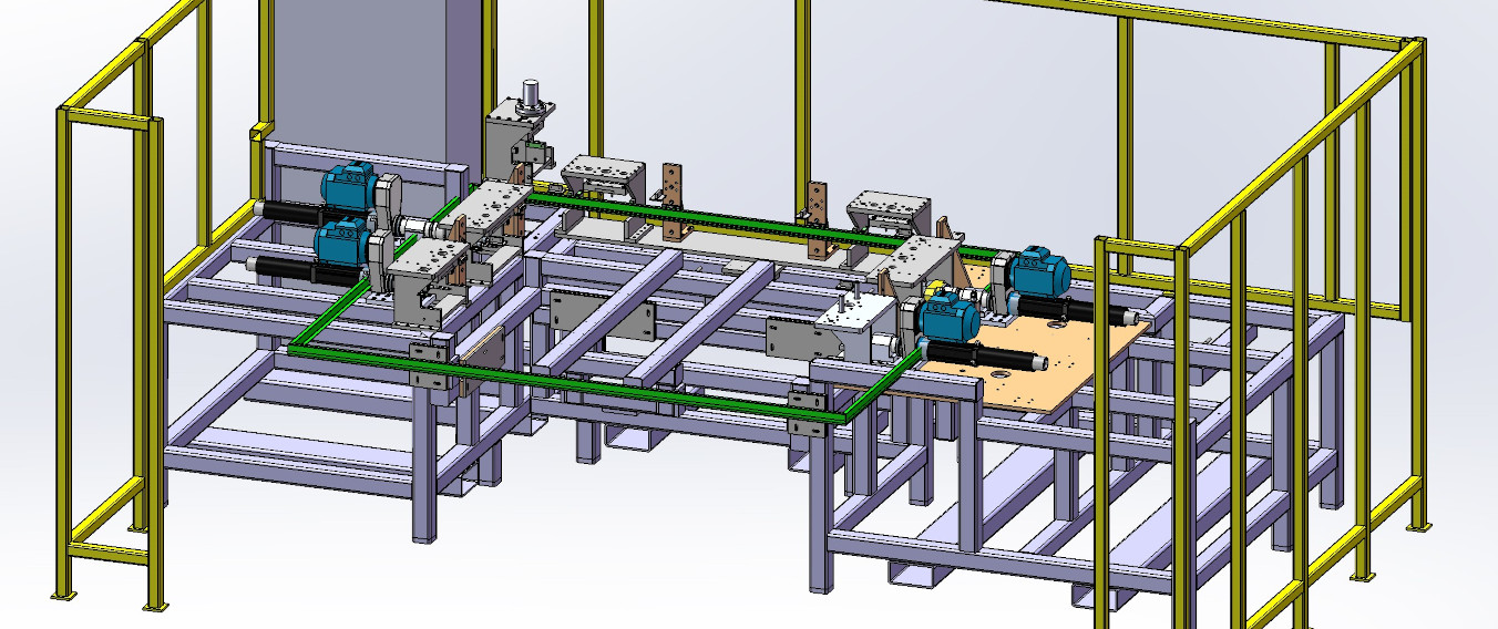
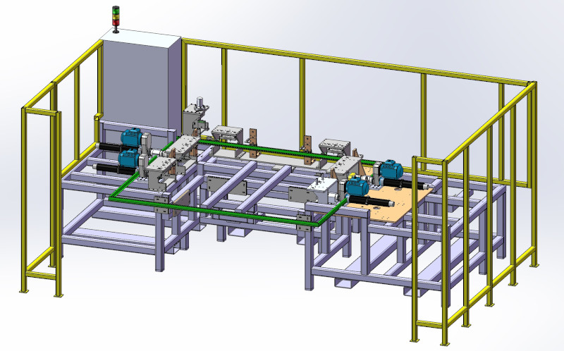
TQC designed an automatic drilling and punching machine with four electro-pneumatic spindle units (2 single-spindle, 2 twin-spindle) mounted horizontally on left and right sides. Hydraulic cylinders punch multiple holes simultaneously. Pneumatic clamping secures fabrications in location tooling. Manual handwheel adjustment changes machine width accommodating fabrication size variants, with automatic rear hole position adjustment maintaining alignment. Slide mechanisms retract drilling units for tool access. Swarf collection drawers under all machining operations enable easy chip removal. PLC control sequences clamping, drilling, and punching operations. Broken tool sensing halts cycles if drill breakage detected. Perimeter guarding with safety mat access prevents operator entry during cycles. Operators load fabrications, initiate automatic cycles, and unload finished parts.
Technical Overview – Automatic Drilling and Punching Machine
Heavy-Duty Framework for Large Fabrications
Structural Platform: Robust steel framework supporting machining forces:
Frame Construction:
- Welded steel box section construction
- Heavy-duty base
- Left and right vertical columns (support drilling units and adjustment mechanism)
- Cross-members tying columns together (structural rigidity)
Why Heavy-Duty Framework:
- Industrial door fabrications large (typical 1-3 metres length, 200-400mm width)
- Part weight 10-50kg (steel construction)
- Drilling thrust forces 500-2000N per spindle (4 spindles = up to 8000N total)
- Hydraulic punching forces 5-20 tonnes per punch
- Framework must resist deflection maintaining hole position accuracy
Adjustment Mechanism:
- Left side fixed to frame (datum reference)
- Right side mounted on linear rails (width adjustment travel)
- Manual handwheel drives leadscrew translating right side
- Position encoder or scale tracks width setting
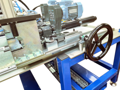
Electro-Pneumatic Drilling Units (4 Spindles)
Horizontal Drilling Configuration: Spindles mounted on left and right sides drilling into fabrication edges:
Spindle Arrangement:
Left Side:
- 1× Single-spindle unit (front position)
- 1× Twin-spindle unit (rear position)
Right Side:
- 1× Single-spindle unit (front position)
- 1× Twin-spindle unit (rear position)
Total Capacity: 6 drills operating simultaneously (2 single + 4 twin = 6 spindles)
Why Horizontal Drilling:
- Industrial door fabrications have holes drilled into edges (mounting hardware attaches through edge)
- Vertical drilling inadequate (cannot access narrow edges)
- Horizontal orientation aligns drill with edge surface
Electro-Pneumatic Actuation:
- Electric motor drives spindle rotation
- Pneumatic cylinder advances spindle into work (feed force control via pressure regulation)
- Combined electro-pneumatic provides:
- Electric motor: High-speed rotation, consistent cutting speed
- Pneumatic feed: Controlled thrust preventing drill breakage, easy retraction
Single vs. Twin Spindles:
- Single-spindle units: One hole per cycle, larger diameter capability
- Twin-spindle units: Two holes per cycle at fixed spacing (common hole patterns, e.g., hinge mounting)
Spindle Mounting:
- Units fixed to columns at predetermined heights
- Height selection based on fabrication hole pattern requirements
- Adjustable if height changes needed (loosen bolts, reposition, re-tighten)
Hydraulic Punching System
Simultaneous Multi-Hole Punching: Hydraulic cylinders punch through metal sheet:
Hydraulic Power Pack:
- Electric motor-driven hydraulic pump
- Reservoir
- Pressure regulation
- Directional control valves routing flow to punch cylinders
Punch Cylinder Configuration:
- Multiple hydraulic cylinders
- Cylinder mounting: Vertical orientation punching downward through horizontal fabrication
- Punch tooling: Hardened steel punches with matching dies
- Punch diameters: 6-25mm typical (depends on application)
Why Hydraulic Punching:
- High Force: Punching through steel sheet requires 5-20 tonnes per hole
- Simultaneous Operation: All punches actuate together (hydraulic flow divides to cylinders)
- Speed: Single stroke completes all holes (vs. sequential drilling)
Punching vs. Drilling Comparison:
- Punching Advantages: Faster (all holes simultaneous), no swarf (sheared disc falls through), longer tool life (shearing vs. cutting)
- Punching Limitations: Fixed hole positions (punch/die locations set in machine), larger diameters challenging (force increases with area)
- Drilling Advantages: Flexible positioning (spindle can locate anywhere), smaller diameter capability
Typical Application:
- Drilling: Variable position holes (custom door configurations)
- Punching: Fixed pattern holes (standard hinge locations, lock cases)
Pneumatic Part Clamping System
Automatic Workpiece Securing: Pneumatic clamps hold fabrication during machining:
Clamping Sequence:
- Load: Operator places fabrication into location tooling (reference pins, stops)
- Initiate Cycle: Operator presses start button
- Clamp: Pneumatic cylinders extend, clamps engage fabrication
- Verification: Pressure switches confirm clamping force achieved
- Machining: Drilling and punching operations execute
- Unclamp: Cylinders retract releasing fabrication
- Unload: Operator removes finished part
Clamping Points:
- Multiple clamps distributed along fabrication length
- Top clamps securing against base tooling (sandwich clamping)
- Side clamps preventing lateral movement during drilling thrust
Why Pneumatic Clamping:
- Speed: Fast extend/retract cycle times (1-2 seconds)
- Force Control: Pressure regulation prevents over-clamping (sheet metal distortion)
- Safety: Automatic actuation keeps operator hands clear
- Interlock: PLC prevents machining operations if clamping not confirmed
Manual Width Adjustment for Variant Fabrications
Multi-Size Accommodation: Handwheel adjustment changes machine width:
Adjustment Mechanism:
Handwheel Operation:
- Located on right side of machine (operator accessible)
- Drives leadscrew (typical 10mm pitch, 1 rotation = 10mm travel)
- Leadscrew translates right-side column along linear rails
- Width range: Typically 200-400mm adjustment travel
Automatic Rear Hole Position Adjustment:
- Mechanical linkage connecting right column to rear drill/punch units
- As right column moves outward (wider fabrication), rear units translate maintaining correct hole spacing
- Preserves hole pattern geometry across size range
Why Manual Adjustment:
- Simple, reliable mechanism (no servo motors, encoders, programming)
- Low cost compared to motorised systems
- Infrequent adjustment (production runs batch same size)
- Operator familiarity (handwheel interface intuitive)
Size Changeover Procedure:
- Unload current fabrication
- Rotate handwheel to new width setting (scale or digital readout indicates position)
- Verify rear units adjusted correctly (visual inspection or position indicator)
- Load new size fabrication, verify fit
- Run first-piece inspection (measure hole positions)
- Proceed with production
Changeover Time: 2-5 minutes (handwheel rotation, verification, first-piece check)
Slide Mechanism for Tool Access
Easy Tool Changeover: Drilling units retract for bit access:
Slide Design:
- Drilling units mounted on linear slides (ball-bearing or roller slides)
- Manual pull-out (operator slides unit away from work area)
- Locking mechanism (pins or clamps) securing unit in operational position
Why Slide Mechanism:
- Drill bit changeover requires access to chuck (difficult with spindle against fabrication)
- Sliding unit creates clearance space (operator accesses chuck, loosens, replaces bit)
- Eliminates need to dismantle spindle mounting
Tool Change Procedure:
- Release locking pins securing drilling unit
- Slide unit outward (50-100mm travel typical)
- Access drill chuck, remove worn bit, install new bit
- Slide unit inward to operational position
- Engage locking pins
- Verify unit secure before resuming production
Tool Life Management:
- Broken tool detection alerts operator to bit replacement need
- Preventive replacement based on hole count (e.g., replace every 500 holes)
Swarf Collection Drawers
Chip Management: Drawers under all machining operations collect swarf:
Drawer Design:
- Sheet metal drawers (100-200mm deep) positioned below drill/punch stations
- Slide-out access (front-mounted handles)
- Capacity: 5-20L depending on production volume
- Material: Steel or plastic (corrosion resistance if coolant used)
Why Swarf Collection:
- Cleanliness: Prevents chip accumulation on machine base
- Safety: Reduces slip hazard from metal chips on floor
- Maintenance: Easy drawer removal and emptying (no machine disassembly)
- Part Quality: Chips swept clear don’t interfere with subsequent part loading
Emptying Frequency:
- Depends on production volume and hole count
- Typical: Empty drawers at shift change or when 80% full
- Visual indicators (transparent drawer sides) or full sensors alert operator
Broken Tool Detection
Automatic Quality Protection: Sensors detect drill breakage:
Detection Methods:
1. Torque Monitoring:
- Current sensors on drill motors monitor torque
- Broken drill causes torque drop (no cutting resistance)
- Controller compares to threshold, flags failure
2. Depth Sensing:
- Proximity sensors measure drill advance distance
- Broken bit doesn’t reach target depth
- Sensor non-contact (capacitive or inductive) or contact (limit switch)
Broken Tool Response:
- Sensor detects failure condition (torque drop or insufficient depth)
- PLC halts cycle immediately
- Alarm indicator alerts operator (visual/audible)
- System prevents unclamp/unload (defective part remains in machine)
- Operator inspects, confirms broken bit, replaces tool
- Operator scraps defective part, resets alarm
- System resumes normal operation
Why Broken Tool Detection:
- Quality: Prevents shipping parts with missing holes (assembly failures in field)
- Efficiency: Immediate detection vs. discovering missing holes downstream
- Safety: Halts cycle preventing further damage from broken bit fragments
PLC Control and Cycle Automation
Programmable Logic Controller: Sequences all machine operations:
Controlled Functions:
- Pneumatic clamp actuation (extend/retract sequence)
- Drilling unit feed (advance/dwell/retract)
- Hydraulic punch actuation (extend/retract)
- Broken tool monitoring and alarm response
- Cycle timing and interlocks
Cycle Sequence:
- Operator Load: Fabrication placed in location tooling
- Start Button: Operator initiates cycle
- Safety Check: PLC verifies guards closed, safety mats clear
- Clamp: Pneumatic cylinders extend, pressure switches confirm
- Drill: Electro-pneumatic units advance, drill holes, retract
- Punch: Hydraulic cylinders extend, punch holes, retract
- Unclamp: Pneumatic cylinders retract
- Cycle Complete: Indicator light signals operator to unload
- Operator Unload: Finished part removed
Interlocks:
- Cannot start cycle unless guards closed
- Cannot enter machine while cycle active (safety mats, light curtains)
- Clamping must confirm before drilling/punching
- Broken tool detection halts cycle
Operator Interface:
- Start/Stop buttons (large, accessible)
- Emergency stop (mushroom button, immediate all-stop)
- Cycle status indicators (idle, running, alarm)
- Alarm display (text or code indicating fault)
Perimeter Guarding with Safety Mat Access
Operator Protection: Guards prevent access during automated cycles:
Guard Configuration:
- Wire mesh or polycarbonate panels enclosing machine perimeter
- Fixed guards on sides and rear (permanent barriers)
- Moveable access door on front (operator load/unload area)
Safety Mat Integration:
- Pressure-sensitive safety mat in front of machine (floor-mounted)
- Operator stepping on mat triggers safety input to PLC
- PLC logic:
- If cycle not running: Mat press has no effect (operator can approach)
- If cycle running: Mat press initiates emergency stop
Why Safety Mats vs. Interlocked Doors:
- Ergonomics: Operator doesn’t open/close door every cycle (faster throughput)
- Visibility: Guards remain in place, operator sees cycle progress
- Multi-Sensor: Mat covers wide area (cannot bypass by reaching around door)
Access Control:
- Mat prevents approach during cycle (drilling, punching active)
- After cycle complete, mat disabled (operator can step on, approach, unload)
- Next cycle cannot start until operator clears mat area (prevents starting with operator inside)
Additional Safety:
- Emergency stop buttons (multiple locations around machine perimeter)
- Rotating beacon (flashing light during cycle active)
- Audible alarm (beep before cycle start, warning operators)
System Specifications – – Automatic Drilling and Punching Machine
- Framework: Heavy-duty welded steel construction
- Drilling Units: 4 electro-pneumatic spindles (2 single-spindle, 2 twin-spindle)
- Drilling Capacity: 6 simultaneous holes (horizontal orientation)
- Spindle Rotation: 1500-3000 RPM (electric motor drive)
- Drill Feed: Pneumatic cylinder actuation with force control
- Punching: Hydraulic multi-cylinder system (5-20 tonnes per punch)
- Hydraulic Power: Motor-driven pump (5-15 kW, 50-200 bar)
- Clamping: Pneumatic cylinders with pressure verification
- Width Adjustment: Manual handwheel with automatic rear position adjustment
- Adjustment Range: Typically 200-400mm width variation
- Tool Access: Slide mechanisms retracting drilling units
- Swarf Collection: Drawers under all machining operations
- Broken Tool Detection: Torque monitoring or depth sensing
- Control: PLC with cycle automation and safety interlocks
- Safety: Perimeter guarding with safety mat access control
- Application: Industrial door metal fabrications (multiple sizes)
Key Features – Automatic Drilling and Punching Machine
Four Electro-Pneumatic Drilling Units: 2 single-spindle + 2 twin-spindle configuration enables 6 simultaneous holes horizontally.
Hydraulic Multi-Punch System: Simultaneous punching of multiple holes faster than sequential drilling, no swarf generated.
Pneumatic Auto-Clamping: Automatic workpiece securing with pressure verification ensuring safe machining operations.
Manual Width Adjustment: Handwheel-driven mechanism accommodates fabrication size variants with automatic rear hole positioning.
Slide Tool Access: Drilling units retract for easy drill bit changeover without spindle dismounting.
Swarf Collection Drawers: Chip accumulation prevention with easy slide-out emptying.
Broken Tool Detection: Automatic cycle halt and alarm if drill breakage detected preventing defective parts.
PLC Cycle Automation: Sequenced clamping, drilling, punching, and unclamping with comprehensive safety interlocks.
Safety Mat Access Control: Pressure-sensitive mat preventing operator approach during active cycles without door interlocks.
Perimeter Guarding: Complete enclosure protecting operators from rotating spindles and hydraulic actuators.
Results – Automatic Drilling and Punching Machine
The automatic drilling and punching machine eliminated manual drilling operations for industrial door fabrications. Four electro-pneumatic spindle units (2 single-spindle, 2 twin-spindle) drill 6 holes simultaneously in horizontal orientation accessing fabrication edges. Hydraulic multi-cylinder punching completes fixed-pattern holes in single stroke.
Pneumatic auto-clamping secures fabrications with pressure verification, eliminating manual clamping inconsistency. PLC control sequences operations preventing operator error in cycle execution. Broken tool detection halts production immediately if drill failure detected, preventing defective parts from advancing downstream.
Manual handwheel width adjustment accommodates multiple fabrication sizes with automatic rear hole position adjustment maintaining pattern geometry. Changeover executes in 2-5 minutes without tooling disassembly. Slide mechanisms retract drilling units creating access for drill bit replacement without spindle dismounting.
Swarf collection drawers capture chips from all machining operations, simplifying cleanup and maintaining machine cleanliness. Safety mat access control prevents operator approach during active cycles while eliminating interlocked door operation, improving ergonomics and throughput.
The automated system replaced slow sequential manual drilling and punching with simultaneous operations, increasing throughput while ensuring consistent hole positioning accuracy essential for industrial door frame assembly alignment.
To view a printer friendly format please click below
Automatic Drilling and Punching Machine
Related Capabilities
This project demonstrates TQC‘s expertise in:
- Heavy-duty fabrication machinery
- Electro-pneumatic drilling systems
- Hydraulic punching equipment
- Multi-spindle machining configurations
- Pneumatic clamping systems
- Manual adjustment mechanisms with automatic compensation
- Swarf collection and management
- Broken tool detection
- PLC control and cycle automation
- Safety mat integration
- Perimeter guarding design
- Industrial door manufacturing automation
If you have an application that could benefit from TQC‘s expertise in automation and automated manufacturing, please contact us by email or phone via the contact details