Robotic Laser Weld Fabrication system
Client: Global Engineering Company
Part: Engineering Metal Seal Rings (Multiple Diameters)
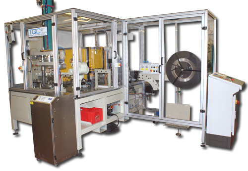
Machine supplied: Fully Automatic Robotic Laser Weld Fabrication System
Robot: Kawasaki 6-Axis with Servo Gripper
Material: Reel-Fed Metal Strip
Operations: Measure → Cut → Form → Laser Weld → Vision Inspect → Polish → Form → Stack
Capacity: Multiple Ring Sizes Without Changeover
The Challenge
A global engineering company producing metal seal rings needed automated fabrication to replace labour-intensive manual processes. The requirements included:
- Precision measurement and cutting from reel-fed metal strip
- Robotic forming of flat strip into circular rings
- Laser welding of ring ends with consistent quality
- Vision inspection verifying weld integrity
- Post-weld polishing and final forming
- Automatic stacking of finished rings
- Multi-size capability (various ring diameters) without tooling changes
- Quality assurance at every manufacturing stage
- High throughput eliminating manual handling
Manual fabrication created inconsistencies in ring dimensions (cutting length variations), weld quality (manual torch control difficult), and finishing (polishing pressure variations). The labour-intensive process limited throughput and increased cost per part. Multi-size production required frequent setup changes, reducing equipment utilisation.
Metal seal rings serve critical applications in aerospace, automotive, and industrial systems where leaks cause:
- System pressure loss (performance degradation)
- Fluid contamination (reliability failures)
- Environmental leakage (regulatory violations)
- Equipment damage from seal failure
Consistent weld quality and dimensional accuracy are essential for seal performance.
The Solution
TQC designed a fully automatic manufacturing cell integrating reel-fed material handling, precision cutting, Kawasaki 6-axis robot, laser welding in guarded enclosure, vision-based weld inspection, sequential polishing and forming stations, and automatic stacking. The robot manipulates parts through all manufacturing stages, transferring rings between stations and diverting rejects to a bin. Vision inspection verifies weld quality before polishing. The system produces multiple ring sizes by adjusting strip length and forming parameters without physical changeover. PLC control coordinates all stations with comprehensive inspection ensuring quality at each stage.
Technical Overview – Laser Weld Robot Cell
Reel-Fed Material Handling System
Continuous Strip Supply: Metal strip material feeds from reel:
Material Characteristics:
- Typical thickness: 0.5-2mm (sheet metal gauge)
- Typical width: 10-50mm (matches ring cross-section)
- Surface finish: Pre-polished or mill finish (depends on application)
- Material properties: Formable alloy allowing bending without cracking
Reel Mounting:
- Motorised uncoiler with tension control
- Dancer arm or load cell maintaining constant strip tension
- Material guide rollers ensuring strip alignment
- Accumulator loop providing buffer during robot transfer
Why Reel Feeding: Coil stock eliminates:
- Material handling between operations
- Bar stock alignment and loading
- Scrap from cut-off ends
- Storage space for individual blanks
Continuous feeding enables uninterrupted production.
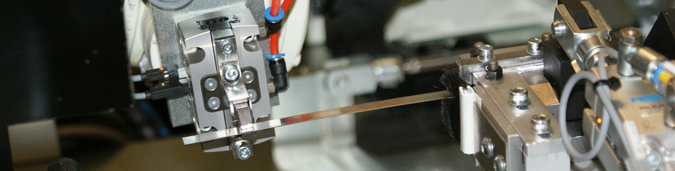
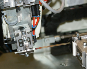
Precision Measurement and Cutting Station
Strip Length Measurement: Encoder-driven measuring system determines cut length:
Measurement Process:
- Encoder Integration: Precision rotary encoder on drive roller tracks strip advance
- Length Calculation: PLC calculates strip position based on encoder pulses
- Size Selection: Operator selects ring diameter via HMI; PLC calculates required strip length (circumference = π × diameter)
- Feed-to-Length: Strip advances until encoder reaches target count
- Stop and Cut: Drive roller halts, cutting mechanism actuates
Cutting Mechanism:
- Pneumatic driven blade
- Hardened tool steel cutting edge
- Minimal burr (clean cut essential for weld quality)
- Cut perpendicularity: ±0.5° (ensures ring ends meet evenly)
End Presentation: After cutting, the strip leading end presents for robot pickup:
- Cut strip remains in position
- End positioned at known location for robot gripper
- Strip length verified by encoder (comparison to target)
Why Precision Measurement: Ring circumference determines seal fit. Variation in strip length creates:
- Undersized rings: Excessive tension, installation difficulty
- Oversized rings: Inadequate sealing pressure, leaks
- Weld gap variation: Inconsistent weld strength
Encoder measurement achieves ±0.1mm repeatability.
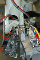
Kawasaki 6-Axis Robot with Servo Gripper
Robotic Material Manipulation: Kawasaki 6-axis articulated robot handles parts through all manufacturing stages:
Robot Specifications:
- Industrial 6-axis articulated arm
- Repeatability: ±0.05mm (critical for weld alignment)
- Work envelope: Covers all manufacturing stations
- Speed: Optimised motion paths between stations
Servo-Mounted Gripper Design: Custom end-of-arm tooling with integrated servo:
Gripper Configuration:
- Primary gripper: Grips strip leading end from cutting station
- Servo-actuated secondary gripper: Opens/closes to capture trailing end during forming
- Servo positioning: Rotates or translates to control ring diameter during forming
- Compliance: Spring-loaded fingers accommodate material springback
Why Servo Integration: Forming circular rings from flat strip requires:
- Leading end grip (robot wrist holds)
- Trailing end capture (secondary gripper closes on opposite end)
- Diameter control (servo positions secondary gripper distance from primary)
- Angular positioning (servo rotates gripper to align ends for welding)
Fixed grippers cannot accomplish these simultaneous operations.
Ring Forming Process
Transforming Flat Strip to Circular Ring: Robot manipulates strip into ring shape:
Forming Sequence:
1. Strip Pickup:
- Robot positions primary gripper at cutting station
- Gripper closes on strip leading end
- Robot lifts, extracting strip from guides
2. Arc Formation:
- Robot executes programmed path bending strip into arc
- 6-axis motion controls bend radius and plane
- Material naturally follows path (elastic deformation)
3. Trailing End Capture:
- As strip forms arc approaching circle, trailing end nears primary gripper
- Servo-mounted secondary gripper opens
- Robot positions trailing end into secondary gripper
- Secondary gripper closes, securing both ends
4. Ring Closure:
- Robot adjusts wrist position bringing ends together
- Servo gripper rotates or translates for precise end alignment
- Gap between ends: 0.1-0.3mm (optimal for laser welding)
- End faces parallel and flush (within 0.05mm)
Forming Challenges Addressed:
Material Springback: Metal strip elastically returns toward flat after bending:
- Robot overbends slightly (5-10° additional rotation)
- Secondary gripper servo compensates for springback
- Final ring diameter within ±0.5mm tolerance
End Alignment: Weld quality depends on precise end positioning:
- 6-axis robot provides positioning flexibility
- Servo gripper fine-tunes angular and radial alignment
- Vision system (at weld station) verifies alignment before welding
Laser Weld in Guarded Enclosure
Precision Joining of Ring Ends: Laser welding creates high-strength joint:
Laser Weld Station Design:
Fully Guarded Enclosure:
- Class 1 laser safety enclosure with interlocked access doors
- Extraction system removing welding fumes
- Shielding windows (laser-specific wavelength filters) for operator viewing
Indexing Mechanism:
- Robot transfers formed ring to weld station fixture
- Fixture rotates ring positioning weld joint at laser focal point
- Servo-driven indexer with encoder feedback
Laser Welding Process: Confidential
Why Laser Welding:
Precision: Small heat-affected zone minimises distortion:
- TIG or MIG welding heats larger area causing ring diameter changes
- Laser’s concentrated energy preserves ring geometry
Speed: Short cycle time (2-4 seconds total) maintains throughput
Strength: Full-penetration welds achieve base material strength
Consistency: Automated laser parameters eliminate manual torch variation
No Filler Required: Autogenous welding (no filler wire) for clean joints
Vision-Based Laser Weld Inspection
Quality Verification Before Polishing: Vision system inspects weld immediately after welding:
Inspection Station Design:
- Industrial camera with telecentric lens (eliminates perspective distortion)
- LED ring light with coaxial illumination (highlights surface features)
- Programmable inspection algorithms
Inspection Criteria:
1. Weld Penetration:
- Measure weld bead width
- Verify consistent bead profile along joint
- Compare to specification (e.g., 1.5-2.0mm bead width)
2. Weld Defects:
- Porosity: Gas bubbles visible as dark spots in bead
- Undercut: Grooves at weld edges indicating excessive penetration
- Spatter: Molten droplets outside weld zone
- Incomplete Fusion: Gap between end faces (weld didn’t fully join)
3. Alignment Verification:
- Measure offset between ring ends at weld
- Excessive offset (>0.2mm) indicates forming or fixturing problem
Pass/Fail Decision:
- All criteria within limits: Pass (proceed to polishing)
- Any criterion outside limits: Fail (robot diverts to reject bin)
Why Vision Inspection Before Polishing:
- Polishing obscures weld defects (cannot inspect after)
- Early rejection prevents wasting polishing consumables and time
- Data logging identifies weld parameter drift for preventive adjustment
Inspection Speed: 1-2 seconds (image capture, processing, decision)
Sequential Polishing and Forming Stations
Post-Weld Finishing: Rings pass through multiple stations refining geometry and surface:
Station Sequence Overview:
Station 1: Weld Bead Grinding
Station 2: Circular Forming
Station 3: Surface Polishing
Station 4: Final Sizing
Station Design:
- Automated actuation (no operator intervention)
- Cycle sensors confirm operation complete before robot retrieval
- Modular design (stations added/removed based on product requirements)
Automatic Stacking of Finished Rings
Outfeed Stack Magazines: Completed rings stack vertically in magazines:
Magazine Design:
- Spring-loaded base supporting ring stack
- Guide posts preventing stack collapse
- Full magazine sensor alerts operator for removal
Stacking Process:
- Robot picks finished ring from final forming station
- Robot positions above magazine stack
- Ring lowers onto previous ring (or magazine base if empty)
- Spring-loaded base descends maintaining top-of-stack position
- Robot releases, withdraws
Why Stacking:
- Orderly collection eliminates bin-dumping damage
- Rings remain clean (no contact with bin walls or other parts)
- Count verification (magazine position indicates quantity)
- Easy operator removal (entire stack lifts from magazine)
Multi-Size Handling: System likely includes:
- Multiple magazines (one per ring size)
- Robot selects destination based on active product recipe
- Size changeover: Operator initiates new size via HMI, system switches magazine
Reject Handling
Automatic Diversion of Failed Parts: Rejects route to separate bin:
Reject Points:
- Measurement/cutting station: Encoder detects incorrect length
- Forming: Robot gripper sensors detect material slip or breakage
- Weld inspection: Vision identifies defects
- Polishing/forming: Sensors detect jamming or incomplete operation
Reject Transfer:
- Robot identifies reject flag in PLC
- Instead of normal station sequence, robot diverts part to reject bin
- Reject bin positioned within robot work envelope
- Part dropped into bin (no precise placement required)
Reject Analysis:
- PLC logs reject mode (weld defect, dimension error, etc.)
- Operator reviews reject data identifying process issues
- High reject rates trigger alarms for investigation
Multi-Size Production Capability
Size Changeover Without Physical Tooling Change:
Size Selection:
- Operator selects ring diameter via HMI touchscreen
- PLC loads corresponding recipe (parameters for selected size)
Recipe Parameters:
- Strip length (calculated from diameter)
- Robot forming path (arc radius matches ring diameter)
- Servo gripper position (controls ring diameter during forming)
- Laser weld parameters (may adjust for different heat dissipation)
- Forming die selection (if multiple dies installed) or die position
- Stack magazine selection
Recipe Switching:
- Completes current ring in process
- Switches to new recipe for next cycle
- No manual tooling changes required
Size Range: System handles diameter variation (e.g., 50-200mm) limited by:
- Robot gripper maximum opening
- Forming station die capacity
- Magazine storage dimensions
Production Flexibility: Enables:
- Mixed batches (switch sizes on demand)
- Small batch production (no changeover cost)
- Quick response to customer orders
PLC Control and Station Monitoring
Integrated Cell Control: Programmable Logic Controller coordinates all operations:
Controlled Equipment:
- Material feed motor and encoder
- Cutting mechanism
- Kawasaki robot (via digital I/O and Ethernet)
- Servo gripper positioning
- Laser welding system
- Vision inspection system
- Polishing/forming station actuators
- Magazine stacking mechanism
Operator Interface:
- HMI touchscreen displaying cell status
- Ring size selection menu
- Production count by size (completed, rejected)
- Reject rate trending by failure mode
- Station status indicators (operating, idle, fault)
- Recipe management (save/load/edit parameters)
Station Monitoring:
- Each station reports operation complete via sensors
- Cycle time monitoring (excessive times trigger alarms)
- Consumable tracking (polishing belt usage, laser shot count)
- Preventive maintenance alerts
Quality Documentation:
- Data logging for each ring (size, weld parameters, inspection results)
- Batch traceability (correlates production time to material reel)
- Statistical process control (dimension trending, weld quality)
System Specifications – Laser Weld Robot Cell
- Configuration: Fully automatic manufacturing cell
- Robot: Kawasaki 6-axis articulated arm with servo-mounted gripper
- Material: Reel-fed metal strip (stainless steel or specialised alloy)
- Material Handling: Motorised uncoiler with tension control
- Measurement: Encoder-driven precision length measurement (±0.1mm)
- Cutting: Actuated cutter with clean cut quality
- Forming: Robotic manipulation with servo gripper control
- Welding: Laser welding in Class 1 guarded enclosure
- Weld Inspection: Vision system with multiple defect detection criteria
- Finishing: Sequential polishing and forming stations
- Stacking: Automatic outfeed to spring-loaded stack magazines
- Size Range: Multiple ring diameters without physical changeover
- Control: PLC with operator HMI and recipe management
- Application: Engineering metal seal rings (aerospace, automotive, industrial)
Key Features – Laser Weld Robot Cell
Reel-Fed Continuous Material: Eliminates manual bar stock loading and scrap from cut-offs.
Encoder Precision Measurement: Strip length controlled to ±0.1mm ensuring ring diameter accuracy.
6-Axis Robotic Forming: Complex manipulation transforms flat strip into circular rings with precise end alignment.
Servo Gripper Integration: Captures both strip ends and controls ring diameter during forming, compensating for material springback.
Laser Welding Quality: Small heat-affected zone preserves ring geometry while achieving full-strength joints.
Vision Weld Inspection: Automated defect detection before polishing prevents wasting time on failed parts.
Sequential Finishing Stations: Grinding, forming, and polishing operations refine geometry and surface finish.
Automatic Stacking: Spring-loaded magazines collect finished rings in orderly stacks for easy removal.
Multi-Size Capability: Recipe-driven production handles various ring diameters without physical changeover.
Comprehensive Quality Monitoring: PLC tracks every manufacturing stage with automatic reject diversion.
Results – Laser Weld Robot Cell
The robotic laser weld fabrication system replaced labour-intensive manual processes with fully automatic production of metal seal rings. Encoder-driven precision measurement achieves ±0.1mm strip length repeatability, ensuring consistent ring diameters.
The Kawasaki 6-axis robot with servo gripper transforms flat strip into circular rings with precise end alignment. Laser welding in a guarded enclosure creates high-strength joints with minimal heat-affected zone, preserving ring geometry that TIG or MIG welding would distort.
Vision-based weld inspection detects porosity, undercut, spatter, and incomplete fusion before polishing. Early rejection prevents wasting finishing operations on defective parts and enables rapid process correction.
Sequential polishing and forming stations refine weld geometry and achieve specified surface finish for seal applications. Automatic stacking in spring-loaded magazines provides orderly collection and count verification.
Multi-size production capability enables batch switching without physical changeover. Recipe-driven parameter adjustment accommodates various ring diameters, improving equipment utilisation and reducing lead times.
The automated cell eliminated manual measurement inconsistencies, weld quality variations, and labour costs while achieving high throughput and comprehensive quality documentation for critical sealing applications.
Following welding, the ring is passed through a series of polishing and forming stations to complete the finished product. The final operation is to transfer completed parts to outfeed stack magazines. The control system monitors every station with part inspection included to ensure correct part production.
Throughout the system running, the robot manipulates parts between stations with any reject parts passed to a reject bin. The system manufactures several different sizes of rings.
To view a printer friendly format please click below
Robotic Laser Weld Fabrication System
Related Capabilities
This project demonstrates TQC‘s expertise in:
- Robotic fabrication systems
- Kawasaki 6-axis robot integration
- Servo gripper design and control
- Reel-fed material handling
- Encoder-based precision measurement
- Laser welding automation
- Class 1 laser safety enclosure design
- Vision-based weld inspection
- Sequential manufacturing stations
- Automatic stacking systems
- Multi-size production flexibility
- PLC control with recipe management
- Quality monitoring and traceability
If you need robotic cell with laser welding and automated inspection, contact TQC to discuss your requirements.