Automated Assembly & Test System for Timing Chain Tensioner
Machine supplied: Fully Automated Assembly and Test Solution
Client: Leading Power Transmission Component Manufacturer.
Part: Chain Tensioner
Throughput: 225 assemblies per hour
The Challenge
A leading power transmission component manufacturer needed to automate assembly of timing chain tensioners while maintaining strict quality control. The complex assembly requires 11 different components with critical functional testing, precision pressing operations, and 100% verification of assembly integrity.
The Solution
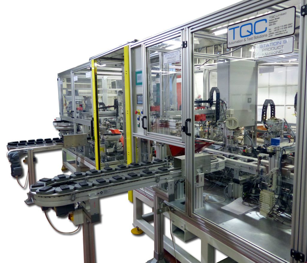
TQC designed and built a 10-station palletized assembly and test system that sequentially assembles, tests, and marks chain tensioners. The system integrates automated part feeding, hydro-pneumatic pressing, functional testing, and quality verification to ensure only conforming assemblies reach the customer.
Technical Overview
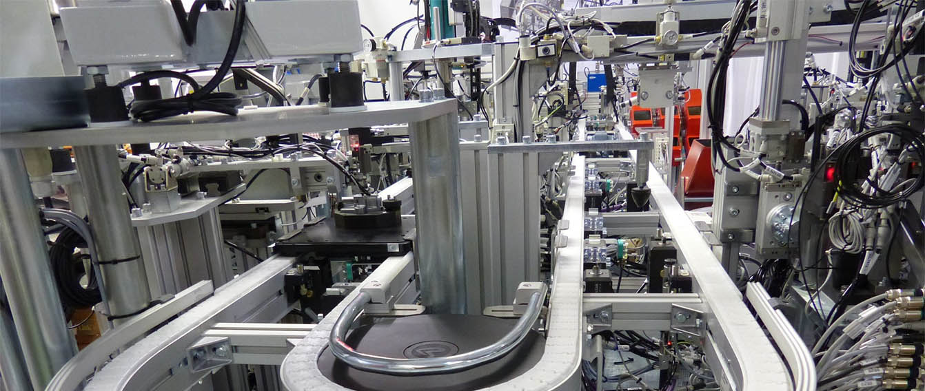
The automated assembly system uses a pallet conveyor architecture with three interconnected loops to handle components through the complete assembly and verification sequence. Main body castings are manually loaded to a pallet infeed loop. The system assembles 11 components per unit through 10 sequential stations, performing functional tests and quality checks at critical points.
Automated Assembly and Test Stations located around the Pallet Conveyor carry out the following –
Automated Assembly Station 1: Gasket Pick and Place
Gaskets are magazine-fed and pneumatically placed onto body castings. Vision systems verify gasket presence and orientation. A manual intervention area allows operators to address any feed issues without stopping the line.
Automated Assembly Station 2: Body Infeed and Check Valve Test
Main body castings transfer from the infeed loop to the assembly pallet system. The check valve undergoes functional testing to verify operation before assembly proceeds. Failed bodies are automatically rejected.
Automated Assembly Station 3: Plunger and Spring Assembly
The plunger spring is measured to verify free length before assembly. A servo-driven mechanism inserts the spring and plunger as a subassembly. Position sensors confirm proper seating.
Automated Assembly Station 4: Cam Component Installation
The cam spring, cam, and cam pin are loaded in sequence. The cam spring is positioned, followed by cam placement and pin insertion. Vision systems verify component presence and alignment.
Automated Assembly Station 5: Cam Pin and Link Plate Press
A hydro-pneumatic press secures the cam pin and link plate with controlled force. The system monitors both press load and final position to verify proper installation. Out-of-spec assemblies are flagged for rejection.
Automated Assembly Station 6: Assembly Validation and Stopper Pin
The partial assembly undergoes functional validation to confirm proper cam operation. The stopper pin is then inserted and position-verified before the assembly continues.
Automated Assembly Station 7: Axi-Rad Insertion
Axi-rad components are bowl-fed and inserted using a servo-driven pick-and-place mechanism. Vision verification confirms proper seating.
Automated Assembly Station 8: Bolt Insertion and Fastening
Bolts arrive in pairs from bowl feeders. Servo screwdrivers install bolts to a specific depth, locating them through the gasket. Torque and angle are monitored to verify proper fastening.
Automated Assembly Station 9: Pass Marking
Assemblies that have passed all verification steps receive percussion marking for traceability. The marking system applies alphanumeric codes as specified by the customer.
Automated Assembly Station 10: Outfeed and Final Inspection
A final bolt length inspection confirms proper installation. Passed assemblies transfer to an outfeed pallet conveyor for manual packing. Failed assemblies are directed to one of six reject chutes based on fault type for root cause analysis.
Pallet Conveyor Systems
Three pallet loops optimize material flow and minimize footprint:
Infeed Loop: Handles main body castings with tooling designed to hold two bodies per pallet, maximizing throughput while reducing conveyor length.
Main Assembly Loop: Larger pallets with integrated part clamps secure the body casting during assembly operations. The clamp compensates for casting variations and ensures consistent positioning at each station.
Outfeed Loop: Completed assemblies transfer to the outfeed conveyor for buffering before manual packing.
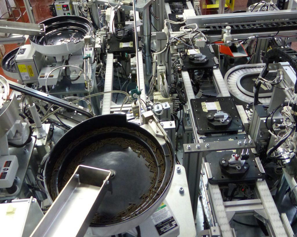
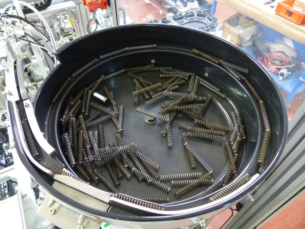
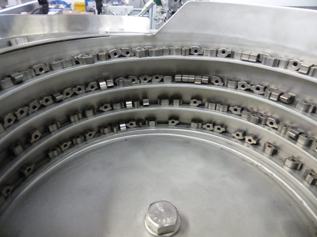
Automated Part Feeding
Eleven vibratory bowl feeders supply components in bulk. Each feeder includes:
- Linear tracks for part orientation and delivery
- Escapements for controlled part presentation
- Low-level sensors that alert operators when refilling is needed
- Continuous operation capability (bowls can be refilled while running)
Automated Assembly Process Technology
Parallel Operations: Several stations perform offline subassembly operations that complete while the main conveyor indexes, reducing overall cycle time.
Precision Pressing: Hydro-pneumatic presses provide controlled force application with real-time load and position monitoring. This ensures consistent press-fit operations without part damage.
Servo-Driven Fastening: Servo screwdrivers monitor torque, angle, and depth to verify proper bolt installation. The system detects cross-threading, stripped threads, or missing fasteners.
Multi-Axis Pick and Place: Pneumatic and servo actuators handle complex part orientations and insertion angles as required by the assembly geometry.
Process Verification & Part Marking
The control system tracks each tensioner through all stations and maintains a pass/fail status. Verification methods include:
Vision Systems: Verify component presence, orientation, and positioning at critical assembly steps.
Functional Testing: Check valve operation and cam mechanism function are tested before final assembly.
Force/Position Monitoring: Press operations are validated through load cells and linear position feedback.
Dimensional Checks: Key dimensions verified at multiple stations to ensure assembly integrity.
Fault Classification: Failed assemblies are sorted into six reject categories, enabling rapid identification of process issues.
The final process prior to unloading is part marking of the tensioner using a percussion marker. All failures are unloaded into one of 6 reject chutes dependent on the type of fault.
Automated Assembly Control System
The system runs on an Omron PLC with touchscreen HMI interface, providing real-time production monitoring, fault diagnostics, reject tracking by category, and cycle count tracking.
System Specifications
- Cycle Time: 16 seconds per assembly
- Output Rate: 225 assemblies per hour
- Assembly Components: 11 parts per tensioner
- Stations: 10 sequential assembly and test operations
- Part Feeders: 11 vibratory bowl feeders plus magazine feeder
- Quality Verification: Functional testing, vision inspection, force/position monitoring
- Reject Sorting: 6 categories for fault analysis
- Control: Omron PLC with HMI
Results
The automated assembly and test system eliminated manual assembly bottlenecks and achieved the target throughput of 225 units per hour. Integrated functional testing and quality verification at multiple stations ensure only conforming assemblies are marked and shipped, reducing field failures and customer returns.
Related Capabilities
This project demonstrates TQC‘s expertise in:
- Complex multi-station assembly automation
- Pallet conveyor system design
- Hydro-pneumatic pressing with force monitoring
- Automated functional testing
- Vibratory bowl feeder integration
- Servo-controlled fastening and insertion
- Vision-based quality verification
- Assembly automation for automotive powertrain components
To view a printer friendly format please click below
Chain Tensioner Automated Assembly System
If you have an application that requires complex assembly automation with integrated testing and quality verification, contact TQC to discuss your requirements.