
Aircraft Wing Fuel Tank & Pipework Test Equipment
Client: Leading Aircraft Wing Manufacturer
Part: Aircraft Wing Fuel Tanks and Pipework (Fuel, Hydraulic, Fire Extinguisher Systems)
Machine supplied: 3 Bespoke Freestanding Portable Semi-Automatic Test Systems
Systems: (1) Hydrogen Tracer Gas Leak Test Bench, (2) Fuel Pipe Leak Test Bench, (3) Hydraulic Pipework Test Bench
Test Pressures: 2 psig to 4,500 psig Across Systems
Control: Dual PC Systems with Production Visual Aids, Barcode Traceability, MIS Integration
Compliance: Aerospace Specifications, Safety Interlocks, Operator Protection
The Challenge
A leading aircraft wing manufacturer required comprehensive testing equipment for integral fuel tanks and pipework systems within carbon fibre wing structures. The requirements included:
- Leak testing large-volume (thousands of litres) carbon fibre fuel tanks
- Detection of leaks through seams, rivets, and dry bay boundaries
- Blockage and pressure testing of fuel, fire extinguisher, and hydraulic pipework
- Test pressure range from 2 psig (fuel tanks) to 4,500 psig (hydraulic systems)
- Flushing and cleanliness verification of hydraulic systems (Reynolds 4000 turbulent flow)
- Operator guidance through complex multi-step test sequences
- Traceability via barcode scanning (wing serial numbers, operator IDs)
- Integration with management information systems for test protocol downloads and results archiving
- Safety systems preventing over-pressurisation and asphyxiation hazards
- Flexible test sequences modifiable by authorised engineers
Aircraft wing fuel and hydraulic systems present critical safety challenges:
- Fuel leaks create fire hazards (ignition sources in wing structure)
- Cross-contamination between tanks compromises fuel quantity gauging
- Dry bay leakage introduces fuel vapour into non-sealed wing sections
- Hydraulic leaks cause flight control failures (ailerons, flaps, spoilers)
- Blockages in fire extinguisher lines prevent fire suppression
- Contaminated hydraulic fluid damages servo valves and actuators
Manual testing couldn’t achieve the repeatability, documentation, and safety required for aerospace production. The company needed integrated systems addressing all wing testing requirements with full traceability.
The Solution
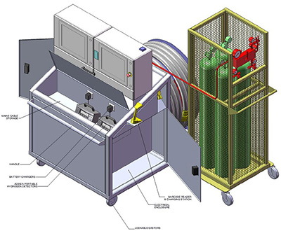
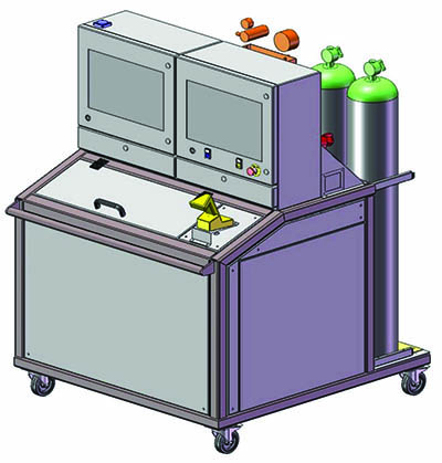
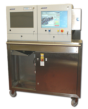
TQC designed three integrated freestanding test systems: (1) Hydrogen tracer gas leak test bench detecting leaks in large carbon fibre fuel tanks using a hydrogen mixture with automatic gross leak pre-screening and dual sniffer probe verification; (2) Fuel pipe leak test bench performing blockage detection and pressure decay testing (20-1,000 psig) on fuel, fire extinguisher, and pneumatic pipework; (3) Hydraulic pipework test bench using Moog electronic pump for turbulent flow flushing (Reynolds 4000), particle count cleanliness verification, and hydrostatic pressure testing to 4,500 psig. All systems feature dual PC control with production visual aids guiding operators through dressing, testing, purging, and undressing sequences. Barcode scanning tracks wing serial numbers and operator IDs. Integration with client MIS enables test protocol downloads and results archiving. Safety systems include pressure relief valves, oxygen/hydrogen monitoring, and interlock logic preventing unsafe operations.
For a printer friendly copy of this page, please click below
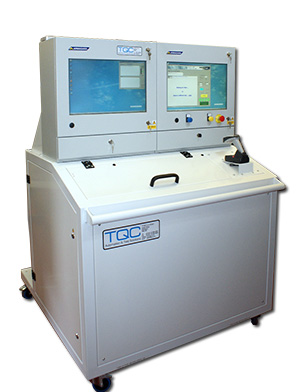
Aircraft Wing Fuel Tank & Pipework Test Equipment
Aircraft Wing Hydrogen Tracer Gas Leak Test Bench
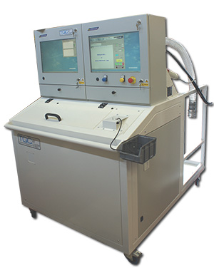
This system is designed to test the integral fuel tanks within the wing structure. The test system checks for leaks
- from the internal tanks to the outside through the
- various seams and rivets in the aircraft wing
- between the two main tanks
- from each tank into a dry bay within the wing
The test equipment includes a series of fittings and sealing bungs specifically designed to blank off the wing structure orifices and support the leakage testing
The test system consists of 2 hydrogen sniffing instruments with a gas dosing and circulation system. This is all controlled by a sophisticated double PC system with Production Visual Aid images and text to guide the test engineer through the complex set of operations to be performed on the aircraft wing under test.
The wings are subjected to an automatic ‘gross leak’ pressure decay test before the hydrogen tracer gas-sensitive leak check is performed.
The system also has a bar code scanner to identify both the wing and the test operator. The system interfaces to the clients Management Information System for archiving test results, downloading test protocols written offline and for authorisation of test personnel.
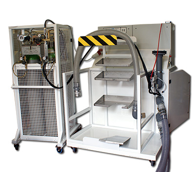
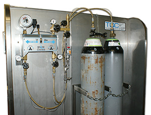
The gas handling system uses a four gas bottle supply system of 5% Hydrogen in 95% Nitrogen with automatic changeover. The wing tanks, being many thousands of litres need a significant supply of test gas even though the wing test pressure is only 2 psig. The gas handling system has gas pressure monitoring to indicate when a gas bottle changeover has occurred.
The gas handling system also includes a circulation system to ensure an even mixture of the test gas throughout the tank under test. While the wing is pressurised, the pressure is monitored to ensure that there is no gross leak to prevent a significant loss of test gas.
Safety is of paramount importance, and so the gas handling systems are fitted with pressure monitoring and pressure relief systems to prevent over pressurisation. In addition, the level of hydrogen and oxygen is monitored to not only ensure a homogenous gas mixture but also to ensure that the tank environment is safe for operators at the end of the purge cycle and does not present any danger of asphyxiation.
When testing a specific tank, the operators are instructed by the control system displaying production visual aids and text instruction through the processes of :-
- ‘dressing’ the wing—connections, sealing bungs, jumpers
- gross leak test by pressure decay monitoring
- tracer gas pressurisation and mixing
- tracer gas leak test using sniffer probes
- purging
- ‘undressing’ the wing
During the leak testing, the test sequence will not proceed until the operator has confirmed the sniffer probe pass / fail status.
Aircraft Wing Fuel Pipe Leak Test Bench
This machine is a blockage and pressure test system to check pipework through the wing for fluid and pneumatic systems.
- Test pressures range between 20 psig and 1,000 psig of both Nitrogen and compressed air.
- The equipment supplied includes a set of quickfit adapters, blanks and connection pipes to enable rapid connection to the various pipe runs.
- Sophisticated PC control system guides the test engineers through each of the individual tests.
The following tests make up a complete test for the array of pipework in the wing :-
- ‘dressing’ the pipework
- blockage detection of the branches of each pipe run
- Pressure decay leak test
- ‘undressing’ the pipework
Each of the 8 different pipe runs can have a specific test pressure within the 20 to 1000 psig range of the machine.
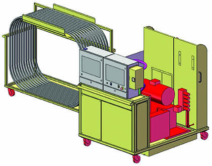
Aircraft Wing Hydraulic Pipework Test Bench
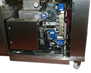
The hydraulic pipework test system is for flushing and pressure testing the hydraulic piping systems and equipment that pass through the wing. The hydraulic test system is based on a sophisticated Moog pump system that uses electronic control to output low pressure / high flow for flushing and high pressure / low flow for pressure testing. Control is again by a sophisticated PC system.
The hydraulic test system had 4 functions :-
- Nitrogen gas gross leak test
- Turbulent flow flushing
- Hydrostatic pressure testing
- Nitrogen gas purge at the end of testing
The hydraulic pipework test includes the following:-
- ‘dressing’ of the pipework, this can include
- jumpers to bypass internal components
- nitrogen gross leak test
- filling with Skydrol and then flushing at Reynolds number of 4000 (turbulent flow) until the contamination particle counter monitor confirms the system cleanliness
- high pressure leak test (pressure decay, upto 4500psi)
- nitrogen purge to recover the Skydrol
- ‘undressing’ the pipework
The result of each test was monitored and recorded onto the PC system for full traceability together with bar code scanning of the wing under test and of the test engineer that is performing the testing. The equipment supplied included a set of adapters, blanks, jumpers and connection pipes, all to aerospace specification, to test the various pipe runs.
System Specifications – Aircraft Wing Test Equipment
System 1: Hydrogen Tracer Gas Leak Test Bench
- Test Type: Hydrogen tracer gas leak detection + pressure decay gross leak screening
- Tracer Gas: 5% H₂ in 95% N₂ (below explosive limit)
- Test Pressure: 2 psig
- Tank Volume: Thousands of litres (large carbon fibre wing fuel tanks)
- Gas Supply: Four-bottle system with automatic changeover
- Detection: Dual hydrogen sniffer probes (ppm sensitivity)
- Circulation: Integrated system for homogeneous gas mixture
- Safety: Pressure relief, H₂/O₂ monitoring, asphyxiation prevention
- Control: Dual PC system with production visual aids
- Traceability: Barcode scanning (wing serial, operator ID), MIS integration
System 2: Fuel Pipe Leak Test Bench
- Test Type: Blockage detection + pressure decay leak testing
- Test Pressure: 20-1,000 psig (eight different pipe runs)
- Test Media: Nitrogen, compressed air
- Pipe Runs: 8 different systems (fuel, fire extinguisher, pneumatic)
- Tooling: Quickfit adapters, blanks, connection pipes (aerospace spec)
- Control: PC system with visual aids
- Traceability: Barcode scanning, MIS integration
System 3: Hydraulic Pipework Test Bench
- Test Type: Turbulent flushing + cleanliness verification + hydrostatic pressure testing
- Pump: Moog electronic control (0-4,500 psig, 0-40 L/min)
- Flushing: Reynolds 4000 turbulent flow in Skydrol
- Cleanliness: Inline particle counter (ISO contamination codes)
- Pressure Test: Up to 4,500 psig hydrostatic
- Recovery: Nitrogen purge for Skydrol recovery
- Control: PC system with visual aids
- Traceability: Barcode scanning, MIS integration
All Systems
- Configuration: Freestanding portable benches
- Operator Guidance: Production visual aids with text instructions
- Flexibility: User-modifiable test sequences (authorised engineers)
- Safety: Pressure relief, gas monitoring, interlock logic
- Application: Aircraft wing fuel tanks and pipework systems
Key Features – Aircraft Wing Test Equipment
Hydrogen Tracer Gas Detection: Cost-effective leak testing of large-volume carbon fibre fuel tanks using 5% H₂/95% N₂ mixture.
Four-Bottle Automatic Changeover: Continuous gas supply during multi-cylinder consumption without test interruption.
Circulation System: Homogeneous tracer gas mixture throughout complex tank geometry ensuring accurate sniffer surveys.
Gross Leak Pre-Screening: Pressure decay testing eliminates major leaks before expensive hydrogen introduction.
Dual PC Control: Separates real-time control from operator visual aids providing robust, graphics-rich guidance.
Multi-Pressure Capability: Single fuel pipe test bench handles 20-1,000 psig across eight different pipe runs.
Blockage Detection: Simultaneous branch pressure monitoring identifies manufacturing debris or installation damage.
Moog Electronic Pump: Automated switching between low-pressure/high-flow flushing and high-pressure/low-flow testing.
Reynolds 4000 Turbulent Flushing: Effective debris removal from hydraulic pipework protecting servo valves and actuators.
Particle Count Verification: Real-time contamination monitoring ensures aerospace cleanliness specifications met before pressure testing.
Nitrogen Purge Recovery: Skydrol displacement reduces fluid waste and dries systems for storage/assembly.
Barcode Traceability: Wing serial and operator ID scanning with MIS integration for certification documentation.
Flexible Test Sequences: User-modifiable procedures accommodating design changes and process improvements.
Results
The three integrated test systems provide comprehensive verification of aircraft wing fuel tanks and pipework. The hydrogen tracer gas bench detects leaks in large carbon fibre fuel tanks (thousands of litres) that air decay or helium testing cannot economically address. Four-bottle automatic changeover maintains gas supply throughout multi-cylinder consumption. Circulation systems ensure homogeneous tracer gas mixture enabling accurate sniffer probe surveys. Gross leak pre-screening via pressure decay prevents hydrogen waste on major sealing failures.
The fuel pipe leak test bench accommodates 20-1,000 psig across eight pipe runs with quickfit tooling enabling rapid connection. Blockage detection identifies manufacturing debris preventing fire extinguisher and fuel system failures. Pressure decay testing verifies joint integrity across fuel, pneumatic, and fire suppression circuits.
The hydraulic test bench uses Moog electronic pump control for automated turbulent flushing at Reynolds 4000, dislodging manufacturing contaminants. Inline particle counting confirms aerospace cleanliness specifications protecting servo valves from erosion and sticking. Hydrostatic testing to 4,500 psig verifies joint integrity and fitting torque. Nitrogen purge recovers expensive Skydrol while drying systems for assembly.
Dual PC control with production visual aids guides operators through complex dressing, testing, purging, and undressing sequences. Barcode traceability integrates with MIS enabling test protocol downloads, results archiving, and operator authorisation verification for aerospace certification requirements.
Safety systems including pressure relief, hydrogen/oxygen monitoring, and interlock logic prevent over-pressurisation and asphyxiation hazards. Flexible test sequences accommodate design changes and process improvements without software redevelopment.
The integrated systems enable the manufacturer to deliver quality-verified wings with comprehensive test documentation meeting aircraft certification requirements.
More Information
For more information about this area of testing please visit the TAMI project webpage here. TAMI, Test for leakage identification on aircraft fluid mechanical installations, was a project TQC was heavily involved with leading partners Airbus Defence and Space (ADS).